-
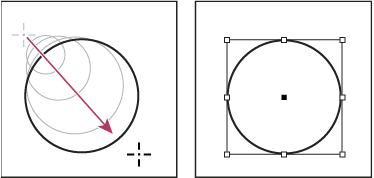
To draw a line or shape, select the Line tool
 , the
Ellipse tool
  , the Rectangle
tool
  , or
the Polygon tool
  . (Click
and hold the Rectangle tool to select either the Ellipse or Polygon
tool.)
. (Click
and hold the Rectangle tool to select either the Ellipse or Polygon
tool.)To draw a placeholder (empty) graphics frame, select the Ellipse Frame tool
 , the
Rectangle Frame tool
  , or
the Polygon Frame tool
  .
.
-
To draw from the center out, hold down Alt (Windows) or Option (Mac OS).
To constrain a line to 45° angles, or to constrain the width and height of a path or frame to the same proportions, hold down Shift as you drag.
To create multiple shapes in a grid, press the arrow keys while holding down the mouse button. See Draw multiple objects as a grid.
To change the number of sides of a polygon, begin dragging, press the Spacebar, and then press the Up and Down arrow keys. Press the Left and Right arrow keys to change the star inset. Press the Spacebar again to return to grid mode.

Opomba:
The result shown above displays a bounding box
around the path. If the Selection tool ![]() was
recently active, you’ll see this bounding box. If the Direct Selection
tool
was
recently active, you’ll see this bounding box. If the Direct Selection
tool ![]() was
more recently active, the path appears with anchor points instead.
was
more recently active, the path appears with anchor points instead.
When using frame-creation tools such as the Rectangle tool or Type tool, you can create a grid of equally spaced frames by using modifier keys.
If you want to use the arrow keys to change the number of sides or star inset while using the Polygon tool, press the Spacebar while holding down the mouse button.
A placeholder shape is an ellipse, rectangle, or polygon that appears in the document window with an X, indicating that it should be replaced by text or an image later.
Opomba:
You can change the crop amount, reference point, and other fitting options for a placeholder frame by choosing Object > Fitting > Frame Fitting Options.
-
For Number of Sides, type a value for the number of sides you want for the polygon.
For Star Inset, type a percentage value to specify the length of a star’s spikes. The tips of the spikes touch the outer edge of the polygon’s bounding box, and the percentage determines the depth of the depression between each spike. Higher percentages create longer, thinner spikes.
You can convert any path into a predefined shape. For example, you can convert a rectangle to a triangle. The stroke settings for the original path remain the same for the new path. If the new path is a polygon, its shape is based on the options in the Polygon Settings dialog box. If the new path has a corner effect, its radius size is based on the size setting in the Corner Options dialog box.
