Learn to use the drawing tools in the Premiere Pro Titler to create various shapes, such as rectangles, ellipses, and lines.
Create shapes
You can use the drawing tools in the Titler to create various shapes, such as rectangles, ellipses, and lines. The Titler includes standard pen tools that resemble pen tools used in Illustrator and Photoshop.
Jon Barrie shows how to use the Titler in Adobe Premiere Pro to create feathered masks in this video on the Creative Cow website.

A. Clipped Corner Rectangle B. Wedge C. Pen Tool D. Ellipse E. Rounded Corner Rectangle F. Rounded Rectangle G. Arc H. Line I. Rectangle

-
Select a shape tool.
Shift-drag to constrain the shape’s aspect ratio.
Alt-drag (Windows) or Option-drag (Mac OS) to draw from the center of the shape.
Shift+Alt-drag (Windows) or Shift+Option-drag (Mac OS) to constrain the aspect ratio and draw from the center.
Drag diagonally across the corner points to flip the shape diagonally as you draw.
Drag across, up, or down to flip the shape horizontally or vertically as you draw.
ملاحظة:To flip the shape after you’ve drawn it, use the Selection tool to drag a corner point in the direction you want it to flip.
Change the shape of a graphic object or a logo
-
Select one or more objects or logos in a title.
-
In the Title Properties panel, click the triangle next to Properties to expand its list, and then choose an option from the Graphic Type menu.ملاحظة:
When you change shapes, the original object anchor points often are lost. To reveal the object anchor points before or after changing the shape, select the object with the Selection tool.
Draw straight segments with Pen Tool
Draw straight lines by clicking Pen Tool in the drawing area. Pen Tool creates object anchor points connected by straight segments.
-
Select Pen Tool.
-
Position the tip of the pen point where you want the straight segment to begin, and click to define the first object anchor point. The object anchor point remains selected (solid) until you add the next point.ملاحظة:
The first segment you draw is not visible until you click a second object anchor point. Also, if lines extend from either side of the point, you’ve accidentally dragged Pen Tool; choose Edit > Undo and click again.
-
Click again where you want the segment to end. (Shift-click to constrain the segment’s angle to multiples of 45°.) Pen Tool creates another object anchor point.
-
Continue clicking Pen Tool to create additional straight segments. The last object anchor point you add appears as a large square, indicating that it is selected.
-
Complete the path by doing one of the following:
To close a path, click the initial object anchor point. A circle appears underneath the pen pointer when it is directly over the initial object anchor point.
To leave the path open, Ctrl-click (Windows) or Command-click (Mac OS) anywhere away from all objects, or select a different tool in the Tools panel.
Draw curves with Pen Tool
Draw curved segments by dragging the object anchor points with Pen Tool. When you use the Selection tool to select an object anchor point connecting curved segments, the segments display direction lines, which end in direction points. The angle and length of the direction lines determine the shape and size of the curved segments. Moving the direction lines reshapes the curves. A smooth point always has two direction lines that move together as a single, straight unit. When you drag the direction point of either direction line on a smooth point, both direction lines move simultaneously. Pen Tool maintains a continuous curve at that object anchor point. In comparison, a corner point can have two, one, or no direction lines, depending on whether it joins two, one, or no curved segments, respectively.
Corner point direction lines maintain the corner by working independently of one another. When you drag a direction point on a corner point’s direction line, the other direction line, if present, does not move. Direction lines are always tangent to (perpendicular to the radius of) the curve at the object anchor points. The angle of each direction line determines the slope of the curve. The length of each direction line determines the height, or depth, of the curve.
-
Select Pen Tool.
-
Position the cursor where you want the curve to begin. Hold down the mouse button.
-
Drag to create direction lines that determine the slope of the curve segment you’re creating. In general, extend the direction line about one third of the distance to the next object anchor point you plan to draw. Shift-drag to constrain the direction line to multiples of 45 °.
-
Release the mouse button.ملاحظة:
The first segment is not visible until you create the second object anchor point.
-
Position Pen Tool where you want the curve segment to end.
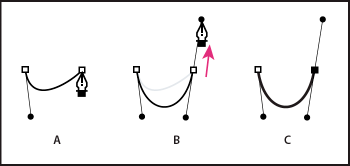
To create a C-shaped curve, drag in a direction opposite to the direction that you dragged to create the previous object anchor point.

Drawing second point in curves 
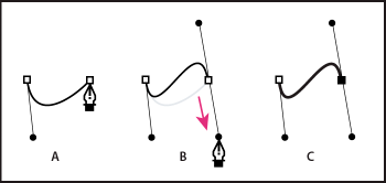
Drawing second point in curves To create an S-shaped curve, drag in the same direction that you dragged to create the previous object anchor point.

Drawing S curves 
Drawing S curves -
Continue dragging Pen Tool from different locations to create additional points.
To close the path, position Pen Tool over the first object anchor point. Click or drag to close the path.
To leave the path open, Ctrl-click anywhere away from all objects or select the Selection tool.
Adjust object anchor points and curves
The Titler includes tools for modifying existing paths. You can add or delete object anchor points on a path. You can also move object anchor points, and manipulate their direction lines to change the curve of adjacent line segments. You can specify not only the path’s thickness but also the shape of each of its ending points. You can also specify its caps, and its corners, or joins.
Add an object anchor point to a path
-
Select the path.
-
Select Add Anchor Point Tool
 .
.
To add an object anchor point without creating or manually adjusting a curve, click where you want to add an object anchor point.
To add an object anchor point and simultaneously move the new point, drag a spot on a path.
Delete an object anchor point
-
Select the path containing the object anchor point.
-
Select Delete Anchor Point Tool
 .
.
-
Click the point that you want to delete.
Adjust an object anchor point
-
Select the path containing the object anchor point.
-
Select Pen Tool
 .
.
-
Position the cursor over the point. When the cursor becomes an arrow with a square next to it, drag the object anchor point to adjust it.
Convert object anchor points from one type to another
You can change the type of object anchor point you have created for a segment.
-
Select the path you want to modify.
-
Select Convert Anchor Point Tool
 and
position the cursor over the object anchor point that you want to
convert.
To convert a corner point to a smooth point, drag a direction point out of the corner point.
To convert a smooth point to a corner point without direction lines, click the smooth point.
To convert a corner point without direction lines to a corner point with independent direction lines, first drag a direction point out of a corner point. Dragging a direction point makes it a smooth point with direction lines. Release the mouse button, and then drag either direction point.
To convert a smooth point to a corner point with independent direction lines, drag either direction point.
ملاحظة:To temporarily change Pen Tool into Convert Anchor Point Tool, position Pen Tool over an object anchor point, and press the Alt key (Windows) or the Option key (Mac OS).
Change the curve of a segment
-
Select the path you want to modify.
-
Select Pen Tool and drag a segment to change its curve.ملاحظة:
Dragging a segment changes the curve by adjusting the direction lines at each end of the segment by the same amount. This technique can change a straight segment into a curved one.
Set options for open and closed Bezier shapes
-
Select a line or an open or closed Bezier shape, and in the Title Properties panel, specify any of the following options:
Graphic type
Adjusts open and closed Bezier shapes to standard shapes. Graphic type can also change a closed Bezier shape to an open one and vice versa. Graphic type must be set to “Filled Bezier” to add fill to a closed shape. For more about adding fill to a closed shape, see Set a fill for text and objects.
Line Width
Specifies the path width, in pixels.
Cap Type
Specifies the type of cap placed at the end of the paths. The Butt option caps paths with square ends. The Round option caps paths with semicircular ends. The Square option caps paths with square ends that extend half the line width beyond the end of the line. This option makes the weight of the line extend equally in all directions around the line.
Join Type
Specifies how the ends of adjoining path segments are joined. The Miter option joins path segments using pointed corners. The Round option joins path segments using rounded corners. The Bevel option joins path segments using squared corners.
Miter Limit
Specifies the point at which the join type switches from mitered (pointed) to bevel (square). The default miter limit is 4. At the default, the join type switches from miter to bevel when the length of the point is four times the stroke weight. A miter limit of 1 results in a bevel join.
ملاحظة:You can apply the options described above to shapes you create with Pen Tool or Line tool. You can apply an inner or outer stroke to any text or graphic object.

